

Product Notice
 Tech Notes
 FAQ
FAQ

Points on connecting wires used in power supplies?
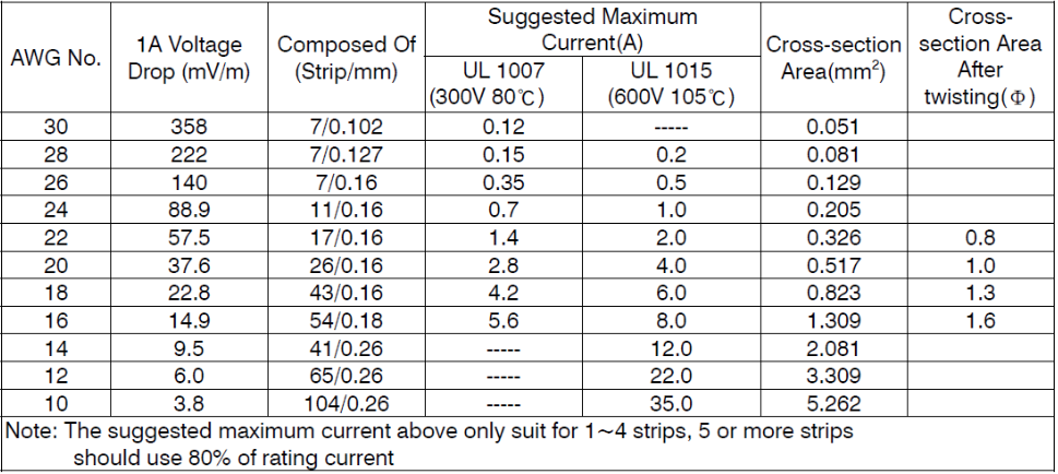
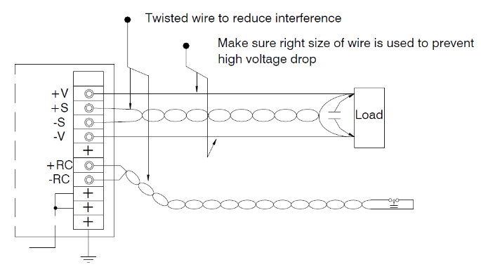
Secondly, voltage drop, which occurs due to the internal resistance of the wires as current flows, resulting in voltage reduction at the load side.
Excessive voltage drop in the line can prevent sufficient voltage from reaching the loads. Based on your system design, you can refer to the table below to find the appropriate wires for use.
 .
.
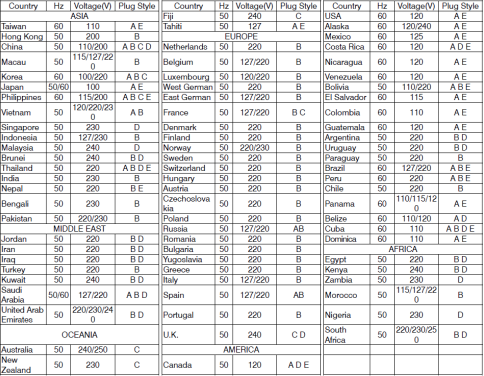
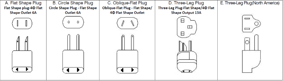
How to select adaptors with the correct AC plug for use in different countries?
It's important to note that AC socket types and voltages differ across countries and regions. Please refer to the table below for information on the AC plug that you need.

A few things you should know before using the Remote Sensing function
If a dynamic load (with a frequency above 1K Hz) is being utilized, capacitors should be added at the output end where the Remote Sensing wires are connected. This is to minimize noise, as Remote Sensing is a highly sensitive function. When selecting a suitable capacitor, two factors must be considered:
a. The Rated Ripple Current should be at least 0.2 times greater than the output current.
b. The Rated Voltage should be higher than the output voltage.

Is it possible to build your own charging curve on the smart chargers when the pre-defined charging curves do not satisfy battery charging requirements?(Video tutorial Inside)
SBP-001 utilizes software in conjunction with its connection to the charger, enabling users to program charging curves.
Adjustable functions are:
Charging parameter adjustment: The values for constant current (CC), constant voltage (CV), float voltage (FV), and tapper current (TC) can be set and modified.
Battery temperature compensation: Various levels of charging voltage compensation are provided for batteries under different temperature conditions.
Timeout setting: A fully programmable timeout during the charging stages allows for setting the charger to shut down, thereby preventing battery overcharge.

What should we pay attention to if system implemented magnetic component?
In cases where distance limitations are unavoidable, installing a well-conducting metal plate (such as a steel plate or copper plate) between the PSU and the magnetic component can help minimize this interference.

How to choose a suitable power supply for a charging application?
The charging current varies depending on the battery's state of charge (full or discharged), and there is a high likelihood of triggering overload protection when the battery is low. Power supplies with overload protection that either hiccup or shut down will cease charging the battery when it is in a low state.
Nevertheless, using a power supply for charging purposes is considered overload usage, and modifications may be necessary. Please reach out to MEAN WELL for further assistance with this request.

What are the applications with serial connection?
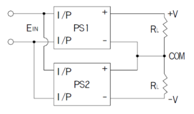
(1) Connection for plus and minus voltage are shown as follow
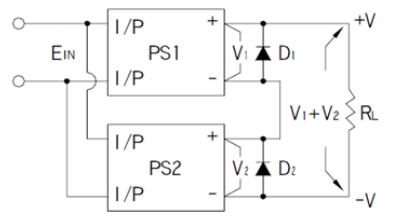
To increase the total output voltage (while keeping the output current the same), it is necessary to connect diodes in parallel at the output side of the driver to prevent damage during startup.
The voltage rating of the diodes should be greater than V1 + V2 (as shown in the figure below). Additionally, the peak forward surge current rating should be greater than the rated current.
* Because part of the signal ground is shorted with output ground, strongly suggest to use isolated signals to achieve control scheme, in order to prevent damage to the product.

What are the requirements of parallel connections? What are the differences between parallel and redundant?
For redundancy purposes, it is recommended to choose PSUs with redundant functionality or implement external redundant modules. Ensure that the differences in output voltage and wiring impedance are minimized as much as possible.
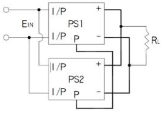
1. Using PSP models as an example, connect the P(LP/CS) terminals together (please refer to the parallel function specifications for details). Prior to connecting to the AC source and loads, ensure that both the input and output are connected in parallel. This is illustrated in the diagram below (note that some SPS may require a minimum load after paralleling).
2. The difference in output voltage between SPS units should be minimized, typically less than 0.2V.
3. The power supplies should first be paralleled using short, large-diameter wiring before being connected to the load.
4. After paralleling, the maximum utilization of total power should be approximately 90% of the rated total power.
5. When power supplies are paralleled, if the load falls below 10% of the rated load of an individual SPS, the LED indicator or signals (such as Power Good, Pok, or Alarm Signal) may exhibit malfunctioning behavior.
6. To ensure effective load current sharing during parallel operation, it is generally recommended not to use more than 4 to 6 power supplies simultaneously.
7. In certain models, the +S and -S terminals should be utilized to mitigate unstable fluctuations in the output voltage.

Why I can not turn on the power supply smoothly when the loads are motors, light bulbs or capacitive loads?

The output ground (GND) and frame ground (FG) is the same point in my system, can MEAN WELL's power supplies be used in such system?