

Product Notice
 Tech Notes
 FAQ
FAQFunctionality Aspect
Application Aspect
Regulation Aspect
Product Aspect
Intelligent Control Aspect
After-sales Service
If you have questions on MEAN WELL’s products, please read the FAQ first. If the listed answers still cannot solve your problems, please contact our Customer Manager, they should reply to you as soon as received your request.
As a dedicated manufacturer of standard power supplies, MEAN WELL provides a wide variety of power supplies to meet different demands from the markets. However, selecting the right products relies heavily on the correct electrical characteristics and specification, we listed the frequently asked questions for your reference.

Functionality Aspect

Notes on choosing a switching power supply?
Ans
1.To increase the reliability of the S.P.S., we suggest users choose a unit that has a rating of 30% more power than actual need. For example, if the system needs a 100W source, we suggest that users choose a S.P.S. with 130W of output power or more. By doing this, you can effectively boost the reliability of the S.P.S. in your system.
2.We also need to consider about ambient temperature of the S.P.S. and whether there is additional device for dissipating the heat. If the S.P.S. is working in a high temperature environment, we need to make some derating to the output power. The derating curve of "ambient temperature" versus "output power" can be found on our spec sheets.
3.Choosing functions based on your application:
· Protection function: Over Voltage Protection (OVP), Over Temperature Protection (OVP), Over Load Protection (OLP), and etc.
· Application function: Signaling Function (Power Good, Power Fail), Remote Control, Remote Sensing, and etc.
· Special function: Power Factor Correction (PFC), Uninterruptible Power Supply (UPS) function.
4.Make sure that the model qualifies for the safety standards and EMC regulations you need.

Can MEAN WELL's power supply be used in the range of 45Hz ~ 440Hz? If YES, what will happen?
Ans
The power supply from MEAN WELL is compatible within a specified frequency range. However, a lower frequency can result in reduced efficiency. For instance, when operating a SP-200-24 under 230VAC and at its rated load, an AC input frequency of 60 Hz yields an efficiency of approximately 84%, whereas a reduction to 50 Hz AC input frequency results in an efficiency of around 83.8%.
Conversely, a higher frequency can decrease the power factor of a power supply system (SPS) equipped with PFC (power factor correction) and increase leakage current. For example, under the same conditions of 230VAC and rated load for a SP-200-24, an AC input frequency of 60 Hz provides a power factor of 0.93 and a leakage current of approximately 0.7mA. However, an increase in AC input frequency to 440 Hz lowers the power factor to 0.75 and elevates the leakage current to approximately 4.3mA.
Conversely, a higher frequency can decrease the power factor of a power supply system (SPS) equipped with PFC (power factor correction) and increase leakage current. For example, under the same conditions of 230VAC and rated load for a SP-200-24, an AC input frequency of 60 Hz provides a power factor of 0.93 and a leakage current of approximately 0.7mA. However, an increase in AC input frequency to 440 Hz lowers the power factor to 0.75 and elevates the leakage current to approximately 4.3mA.

What is minimum load requirement and how can I read it from the spec?
Ans
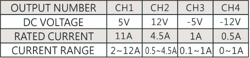
MEAN WELL's multi-output power supplies have certain minimum-load requirements that must be adhered to. Prior to connecting any load, it is crucial to consult the specifications. To ensure the power supply operates correctly, a minimum load is necessary for each output; failure to do so may result in unstable output voltage levels or deviations beyond the tolerance range.
Please refer to the "Current range" section in the specifications, as outlined in the table below: Channel 1 necessitates a minimum load of 2A, Channel 2 requires 0.5A, Channel 3 needs 0.1A, and Channel 4 does not require any minimum load.

Please refer to the "Current range" section in the specifications, as outlined in the table below: Channel 1 necessitates a minimum load of 2A, Channel 2 requires 0.5A, Channel 3 needs 0.1A, and Channel 4 does not require any minimum load.

Why did the power supply shuts down during operation and after turning it off, I can restart the power supply again?
Ans
Generally, there are two scenarios that can lead to the shutdown of a power supply. The first is the activation of the over-load protection (OLP). To address this, we recommend either increasing the rated output power or adjusting the OLP point.
The second scenario is the activation of the over-temperature protection (OTP) when the internal temperature reaches a preset limit. Both of these conditions will trigger the power supply to enter protection mode and shut down. Once these conditions are resolved, the power supply will return to normal operation.
The second scenario is the activation of the over-temperature protection (OTP) when the internal temperature reaches a preset limit. Both of these conditions will trigger the power supply to enter protection mode and shut down. Once these conditions are resolved, the power supply will return to normal operation.

What is the control mechanism for cooling fans?
Ans
Cooling fans generally have a shorter lifespan (with a typical Mean Time To Failure, or MTTF, ranging from approximately 5,000 to 100,000 hours) compared to other components of a power supply. Consequently, modifying the fans' operating method can prolong their operational hours. The most prevalent control strategies are outlined below:
1.Temperature control: When the internal temperature of a power supply, sensed by a temperature sensor, exceeds a predefined threshold, the fan will operate at full speed. Conversely, if the internal temperature falls below the set threshold, the fan will either cease operation or run at half speed. Furthermore, some power supplies utilize a non-linear control method for their cooling fans, allowing the fan speed to vary synchronously with different internal temperatures.
2.Load control: When the loading of a power supply exceeds a predefined threshold, the fan will operate at full speed. On the other hand, if the loading falls below the set threshold, the fan will either cease operation or run at half speed.

What is "Inrush Current"? What will we notice?
Ans
At the input side, there will be a large pulse current (ranging from 20 to 100A depending on the design of the power supply) lasting for about 1/2 to 1 cycle (for example, 1/120 to 1/60 seconds for a 60 Hz AC source) at the moment of power-on, before returning to its normal rating. This "inrush current" occurs every time the power is turned on.
While it won't damage the power supply, we recommend avoiding turning the power supply ON/OFF too quickly within a short period. Additionally, if multiple power supplies are turned on simultaneously, the AC source's dispatching system may shut down and enter protection mode due to the significant inrush current. It is advisable to start up these power supplies one by one or use the remote control function of the power supply to turn them on/off.
While it won't damage the power supply, we recommend avoiding turning the power supply ON/OFF too quickly within a short period. Additionally, if multiple power supplies are turned on simultaneously, the AC source's dispatching system may shut down and enter protection mode due to the significant inrush current. It is advisable to start up these power supplies one by one or use the remote control function of the power supply to turn them on/off.

What is PFC?
Ans
Power Factor Correction (PFC) aims to enhance the ratio of apparent power to real power. Non-PFC models typically have a power factor ranging from approximately 0.4 to 0.6. However, in models equipped with a PFC circuit, the power factor can exceed 0.95. The calculation formulas are as follows: Apparent Power = Input Voltage × Input Current (VA), and Real Power = Input Voltage × Input Current × Power Factor (W).
From an environmental perspective, power plants need to generate power that exceeds apparent power to ensure a stable electricity supply. The actual usage of electricity is determined by real power.
Assuming a power factor of 0.5, the power plant would need to produce more than 2 VA (Volt-Amperes) to satisfy 1 W (Watt) of real power usage. Conversely, if the power factor is 0.95, the power plant only needs to generate slightly more than 1.06 VA to provide 1 W of real power. Incorporating PFC (Power Factor Correction) functionality results in more effective energy savings.
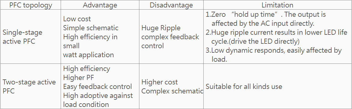
Active PFC topologies can be categorized into single-stage active PFC and two-stage active PFC, with the differences outlined in the table below.
From an environmental perspective, power plants need to generate power that exceeds apparent power to ensure a stable electricity supply. The actual usage of electricity is determined by real power.
Assuming a power factor of 0.5, the power plant would need to produce more than 2 VA (Volt-Amperes) to satisfy 1 W (Watt) of real power usage. Conversely, if the power factor is 0.95, the power plant only needs to generate slightly more than 1.06 VA to provide 1 W of real power. Incorporating PFC (Power Factor Correction) functionality results in more effective energy savings.
Active PFC topologies can be categorized into single-stage active PFC and two-stage active PFC, with the differences outlined in the table below.

What is the difference between -V and COM which are marked on the output side?
Ans
COM (COMMON) means common ground. Please see below:
Single output: Positive pole (+V), Negative pole (-V)
Multiple output (Common ground): Positive pole (+V1, +V2,.), Negative pole (COM)
Single output: Positive pole (+V), Negative pole (-V)
Multiple output (Common ground): Positive pole (+V1, +V2,.), Negative pole (COM)

In MEAN WELL's catalog, we see AC and DC at input, what is it all about?
Ans
Due to different circuit designs, MEAN WELL power supply's input consists of three types as below:
(VAC≒VDC)
a.85~264VAC;120~370VDC
b.176~264VAC;250~370VDC
c.85~132VAC/176~264VAC by Switch; 250~370VDC
· In both a and b input models, the power supply can function correctly with either AC or DC input. Some models necessitate a specific connection of the input poles: the positive pole should be connected to AC/L, and the negative pole to AC/N. Conversely, other models may require the opposite connection, with the positive pole going to AC/N and the negative pole to AC/L. If customers make an incorrect connection, the power supply will not be damaged. Simply reversing the input poles will restore normal operation of the power supply.
· In c input models, please ensure that you correctly switch the 115/230V input. If the switch is set to the 115V side while the actual input voltage is 230V, the power supply will be damaged.

What is minimum load requirement and how can I read it from the spec?
Ans
MTBF (Mean Time Between Failure) and Life Cycle are both indicators used to measure reliability. MTBF can be calculated using two different methodologies: "part count" and "stress analysis". The commonly used regulations for calculating MTBF are MIL-HDBK-217F Notice 2 and TELCORDIA SR/TR-332 (Bellcore). MIL-HDBK-217F is a United States military standard, while TELCORDIA SR/TR-332 (Bellcore) is a commercial regulation.
MEAN WELL employs MIL-HDBK-217F (Stress Analysis) as the foundation for calculating MTBF. The precise definition of MTBF is that, after continuously using the power supply for a specific duration, the average time until the probability of proper operation drops to 36.8% (e-1=0.368). Currently, MEAN WELL utilizes MIL-HDBK-217F to predict expected reliability through Stress Analysis (excluding fans). This MTBF indicates that the probability of the product continuing to operate normally after continuously working up to the calculated MTBF time is 36%.8% (e-1=0.368).
If the power supply is continuously used for double the MTBF time, the probability of proper operation decreases to 13.5% (e-2=0.135). The Life Cycle is determined by estimating the approximate lifespan of the power supply using the temperature rise of electrolytic capacitors under maximum operating conditions. For instance, the RSP-750-12 has an MTBF of 109.1K hours at 25°C, while the Life Cycle of its electrolytic capacitor C110 is 213K hours at an ambient temperature of 50°C.
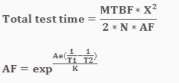
DMTBF (Demonstration Mean Time Between Failure) is a method used to evaluate MTBF. Please refer to the following equation for the calculation of MTBF.
MTBF:Mean Time Between Failure
X2:Can be found in chi-square distribution
N:Number of sampling
AF:Acceleration factor, which can be derived from acceleration factor equation.
Ae=0.6
K(Boltzmann Constant)=(eV/k)
T1:Rated temperature of specification. Note: Kelvin will be the unit use for calculation
T2:The temperature that is used in the meaning of acceleration, and the chosen temperature could not result in physical change in materials. Note: Kelvin will be the unit use for calculation.
MEAN WELL employs MIL-HDBK-217F (Stress Analysis) as the foundation for calculating MTBF. The precise definition of MTBF is that, after continuously using the power supply for a specific duration, the average time until the probability of proper operation drops to 36.8% (e-1=0.368). Currently, MEAN WELL utilizes MIL-HDBK-217F to predict expected reliability through Stress Analysis (excluding fans). This MTBF indicates that the probability of the product continuing to operate normally after continuously working up to the calculated MTBF time is 36%.8% (e-1=0.368).
If the power supply is continuously used for double the MTBF time, the probability of proper operation decreases to 13.5% (e-2=0.135). The Life Cycle is determined by estimating the approximate lifespan of the power supply using the temperature rise of electrolytic capacitors under maximum operating conditions. For instance, the RSP-750-12 has an MTBF of 109.1K hours at 25°C, while the Life Cycle of its electrolytic capacitor C110 is 213K hours at an ambient temperature of 50°C.
DMTBF (Demonstration Mean Time Between Failure) is a method used to evaluate MTBF. Please refer to the following equation for the calculation of MTBF.
MTBF:Mean Time Between Failure
X2:Can be found in chi-square distribution
N:Number of sampling
AF:Acceleration factor, which can be derived from acceleration factor equation.
Ae=0.6
K(Boltzmann Constant)=(eV/k)
T1:Rated temperature of specification. Note: Kelvin will be the unit use for calculation
T2:The temperature that is used in the meaning of acceleration, and the chosen temperature could not result in physical change in materials. Note: Kelvin will be the unit use for calculation.